|
Mitigation measures for telecommunication installations
PART 2: CASE STUDIES
| Case study # |
1.5 |
Download
PDF ( ) ) |
| Title |
Acoustic noise troubles caused by an electric fence
|
| Type of trouble |
Acoustic noise, degradation. |
| Source of trouble |
Electric fence. |
| System affected |
Customer equipment, line. |
| Location |
Customer premises, outdoors. |
| Keywords |
Power transmission line, transformers, screening, mutual coupling
earth connection, optical components, optical insulation.
|
| Version date |
2004-01-01 |
| System configuration |
|
A customer complained about intense
noise troubles on his analogue telephone line. The acoustic
noise was permanent with varying intensity. Because of the
kind of the problem (clicking interference at regular
intervals), it was suspected that the cable (10-pair 0.4-mm
copper cable) was being affected by an electric fence close
to the cable route, which did not make part of this
installation.
An optical fibre cable, with its screen earthed at both
ends, was running parallel to the 10-pair copper cable. The
optical fibre cable, the multiplexer (optical-electrical) and
the 10-pair copper cable ended at the same distribution
point. However, a long electric fence was located in the
neighbourhood of the optical fibre cable, although not at the
copper cable site.
The system configuration of the location is shown in
Figure 1.5-1.
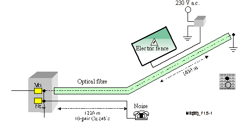
Figure 1.5-1 – System configuration |
| Measurement/Searching techniques/Experiment |
|
The electric parameters of the line were in line with the
requirements. A 148-Vp-p longitudinal voltage line-to-ground
at customer installation was measured (Figure 1.5-2). The
major frequency of the transients was about 8 kHz and
decreased after 2.5 ms (Figure 1.5-3). The transients
repeated at 1.3-second intervals. Measurements were also made
at the distribution point. On the screen of optical fibre
transient, currents with about 27 Ap-p were measured. The
peak-to-peak voltage recorded between the earthing conductor
of the screen and the ground at the distribution point was
340 Vp-p (Figure 1.5-4). The asymmetrical supplying cable of
the electrical fence, which was situated along the route of
optical fibre, was identified as the source inducing the
transients.
Through the screen that was earthed at both sides (screen
resistance 13.5 W), the optical fibre was the source for the
induction into the parallel copper cable. The metallic foil
of the 10-pair cable was earthed on only one side, connected
to the earth of the distribution point.
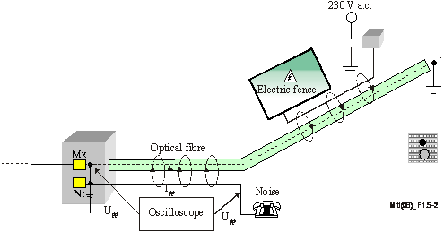
Figure 1.5-2 – Measurement system


Figure 1.5-3 – Voltage transient on Figure 1.5-4 – Voltage transient on the
the copper – cable
screen of the optical fibre
|
| Mitigation method |
|
First, the metallic foil of the 10-pair copper cable was
connected to the main earthing terminal at the customer site.
As a result, the transient voltages were reduced to 1/6 of
the value that had before mitigation (Figure 1.5-6). The
remaining voltage, which was about 23 Vp-p, still caused some
clicking noise. To solve this problem, it was decided to
install a neutralizing transformer at the distribution point.
This led to a decrease of about 3 Vp-p, making the
disturbance vanish.
The buried power supply cable of the fence was poorly
isolated, i.e., the connecting points were not isolated.
Because of the disturbances, the following solution was
found, in agreement with the owner of the electric fence:
increase the distance between the power supply cable of the
electric fence and the optical fibre cable, and properly
isolate the connectors.
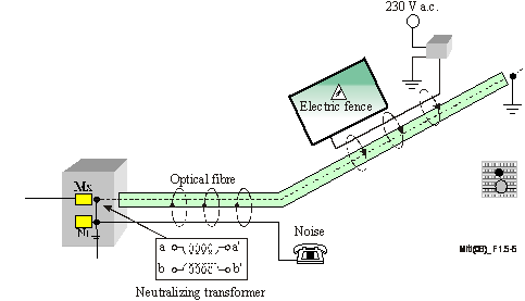
Figure 1.5-5 – Mitigation method
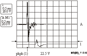
Figure 1.5-6 – Mitigation results |
|
|