International Telecommunication Union   ITU
عربي  |  中文  |  Español  |  Français  |  Русский
 
 Advanced Search Advanced Search Site Map Contact us Print Version
 
Home : ITU-T Home
   
ITU Telecommunication Standardization Sector (ITU-T)
Handbook Contact: tsbedh@itu.int

Mitigation measures for telecommunication installations

PART 2: CASE STUDIES


Case study #

2.8

Download PDF ()

Title

Earth wire voltage drop in telecommunication centre

Type of trouble

Damage.

Source of trouble

Lightning.

System affected

Transmission equipment.

Location

Telecommunication centre.

Keywords

Damage, lightning surge.

Version date

2004-01-01


System configuration
During thunderstorms, several line cards of a multiplex, located in a radio station, were frequently damaged.

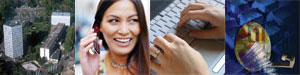
Located on the top of a mountain, the radio station is composed of a 40-m high telecommunication tower and an adjacent 2-floor building (Figure 2.8-1). The antennas on the tower are connected to the radio equipment inside the building by wave-guide cables.

In the building, on the ground floor, there are the entrance of the low voltage power line through an insulation transformer, the power station, and the main earth terminal of the building. On the first floor, there is the radio equipment. On the second floor, there are radio equipment and a multiplex. The latter serves customers located close to the radio station.

The customers are connected to the multiplex by 30 pairs of 9/10 cable. This cable can be defined as a "lightning cable", i.e., the cable can resist high values of direct lightning current. Though it has been installed a long time, lightning never damaged the cable.


Figure 2.8-1 – Radio station


Measurement/Searching techniques/Experiment
An on-site survey was carried out. The survey results are as follows:

A small main distribution frame (MDF) is located on the second floor. Primary protectors, constituted by gas discharge tubes (GDTs), were installed at the MDF between all the cable conductors and the MDF metallic structure. The cable metallic sheath is also connected to the metallic structure of the MDF that is connected to the main earthing terminal (MET) on the ground floor by a bonding conductor.

The bonding mat, i.e., the ground plane, of the radio equipment and multiplex is also connected to the MET by another bonding conductor.

In this installation condition, when overvoltages cause GDTs firing, the voltage drop, caused by the overcurrents flowing in the bonding conductor between the MDF and the MET, will appear at the entrance of the line cards and could cause damages if its peak value is greater than the line card resistibility level defined by Rec. ITU-T K.45 or Rec. ITU-T K.20.


Mitigation method/Results/Conclusion

Because the earth wire voltage drop was probably the source of the line-card damages, the equipotential bonding technique was improved in order to prevent the earth wire voltage drop from being transferred to the equipment interface.

This was easily achieved by installing on the second floor another bonding bar (BB) connected to the MET. The metallic structure of the MDF (i.e., the GDTs' earth) and the bonding mat were directly connected to the second floor's bonding bar.

This installation avoids transferring the earth wire voltage drop to the equipment interface and there is no need to limit its value or to increase the line-card resistibility to lightning overvoltages.

Conclusion: The earth wire voltage drop is not a resistibility problem if equipotential bonding is properly achieved.


Figure 2.8-2 – New bonding configuration


Table of content


Top - Feedback - Contact Us -  Copyright © ITU 2010 All Rights Reserved
Contact for this page : TSB EDH
Updated : 2010-06-29