PARAMETERS FOR TESTING
The most important parameters (subset of 14 analyses) are summarized in a Recommendation ITU-T P.505 “Quality Pie” chart. The selected slices represent the following parameters and requirements (clockwise):
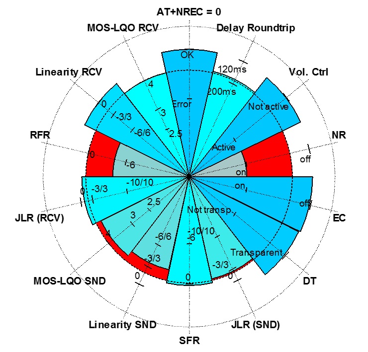 AT+NREC=0 ─ the pie slice indicates the reply of the mobile phone on this command from the reference Bluetooth® interface. The pie slice is scaled between “OK” and “Error”.
- Delay Roundtrip ─ the pie slice represents the measured roundtrip delay of the mobile phone in the Bluetooth® connection. The pie slice is scaled in ms.
- Vol. Ctrl. ─ this pie slice indicates the influence of the phones’ volume control on the signal transmission in downlink. The pie slice is digitally scaled between “Not active” and “Active”.
- NR ─ the pie slice indicates noise reduction in the mobile phone and represents two possible states, the noise reduction disabled as expected (“off” in the Quality Pie) or enabled (“on”). The “NR” should be verified in the Bluetooth® connection after sending the “AT+NREC=0” command.
- EC ─ the pie slice indicates status of echo cancellation algorithm implemented in the mobile phone. The verification of the active echo cancellation algorithm in the mobile phone after receiving the “AT+NREC=0” command from the Bluetooth® reference interface is scaled in a similar way. There are two different stages, “off” (as required) or “on”.
- DT ─ the pie slice indicates the influence of implemented signal processing on double talk performance is represented by the “DT” pie slice. Again, two different stages are possible, the pie slice is scaled between “transparent” (as recommended) or “not transp”.
- JLR (SND) — the pie slice indicates the uplink sensitivity expressed by the Junction Loudness Rating (“JLR (SND)”) scaled in dB.
- SFR – the pie slice represents the violation of the tolerance scheme by the measured sending frequency response (SFR) in dB.
- Linearity SND — the pie slice indicates the gain adjustment (amplification or attenuation) introduced by the mobile phone in the sending (SND) direction. This pie slice is scaled in dB.
- MOS-LQOn,w SND — the pie slice indicates the listening speech quality measured in sending direction using the POLQA algorithm described in Recommendation ITU-T P.863. The scale directly represents the measured MOS-LQOn (narrowband) or MOS-LQOw (wideband) scores.
- JLR (RCV) — the pie slice indicates the downlink sensitivity expressed by the junction loudness rating (JLR) in receiving direction (RCV), scaled in dB.
- RFR — the pie slice represents the violation of the tolerance scheme by the measured receiving frequency response (RFR) in dB.
- Linearity RCV — the pie slice indicates the gain adjustment (amplification or attenuation) introduced by the mobile phone in the receiving (RCV) direction. This pie slice is scaled in dB.
- MOS-LQOn,w RCV — the pie slice represents the listening speech quality in receiving direction expressed by the measured MOS-LQOn (narrowband) or MOS-LQOw (wideband) scores.
LIMITS
Recommendations ITU-T P.1100 (03/2017) and P.1110 (03/2017) established the following limits for the above parameters:
| Parameters | Limit in accordance with Rec. ITU-T P.1100 | Limit in accordance with
Rec. ITU-T P.1110 |
| Delay | 190 ms1) | 190 ms1) |
| JLR SND | 0 ± 2 dB | 0 ± 2 dB |
| JLR RCV | 0 ± 2 dB2) | 0 ± 2 dB2) |
| Linearity SND | JLR SND ± 2 dB | JLR SND ± 2 dB |
| Linearity RCV | JLR RCV ± 2 dB | JLR RCV ± 2 dB |
| SFR | Tolerance scheme | Tolerance scheme |
| RFR | Tolerance scheme | Tolerance scheme |
| Noise Reduction | disabled (± 4 dB) | disabled (± 4 dB) |
| MOS-LQOn,w SND | 4.0 MOS-LQOn | 3.8 MOS-LQOw |
| MOS-LQOn,w RCV | 4.0 MOS-LQOn | 3.8 MOS-LQOw |
| Echo Canceller | disabled (TCLw 20 ± 2 dB) | disabled (TCL 20 ± 2 dB) |
Note:
1) Performance objective: <150 ms
2) No additional volume control shall be active |
METHODOLOGY
The tests are carried out on a mobile phone between two electrical interfaces, i.e. a mobile network simulator on the network side and a Bluetooth® reference interface on the near end side. The Bluetooth® reference interface communicates via the Hands-Free Profile (HFP) to the mobile phone under test. A narrowband and wideband Bluetooth® connection can be setup depending on the capability of the mobile phone, in particular if the mobile phone supports the wideband Bluetooth® connection using the mSBC codec. Tests in a narrowband Bluetooth® connection use the CVSD speech codec.
The tests can be separated to verify the performance of the different communication aspects:
- Tests in the sending direction cover Junction Loudness Rating tests, linearity tests, frequency response tests and listening speech quality tests.
- The corresponding tests in the receiving direction cover the same parameters.
- Echo performance tests are realized by simulating an echo path on the Bluetooth® side. These tests are implemented in order to verify if the implemented echo cancellation signal processing in the mobile phone is disabled as required.
- Background noise transmission tests are analyzed in the sending direction. The main purpose is the verification of whether or not noise reduction is disabled as required.
- Double-talk performance tests are carried out in order to verify if active echo cancellation does not cause undesired effects and degradations by applying test signals in both directions (the receiving and sending direction) simultaneously. The most critical use case is analyzed, that being the signal attenuation in the sending direction caused by the implemented (and possibly active) echo suppression units in the mobile phones.